Dragon 1:35 Sherman k.III

All your builds here...

Moderator: T3hGuppy

Post Reply
User avatar
gaz45
Chief Warrant Officer 3
Posts: 1971
Joined: Mon Jan 06, 2014 3:35 pm
Location: Nottingham uk
Great Britain

Dragon 1:35 Sherman k.III

Post by gaz45 »

This is my entry in this GB

Image

Image

It looks to be a nice kit with some nice detail to it

Sprues

Image

Image

Image

Image

Image

Image

Image

Image

Image

Image

Image

Image

Image

Image

Image

Image

Image

Image

1 piece barrel

Image

Image

Image

Clear parts

Image

A bit of PE

Image

The tracks look nicely detailed

Image

Image

Metal tow cable

Image

Decals

Image

The instructions
The paint callouts are for Mr hobby aqueous, Mr color and model master
Image

Image

Image

Image

Image

Image

Image

Image

That's all for now next up a bit of history
User avatar
gaz45
Chief Warrant Officer 3
Posts: 1971
Joined: Mon Jan 06, 2014 3:35 pm
Location: Nottingham uk
Great Britain

Re: Dragon 1:35 Sherman k.III

Post by gaz45 »

Right here is the history bit

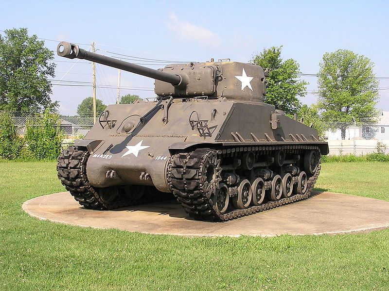
The M4 Sherman, officially Medium Tank, M4, was the most numerous battle tank used by the United States and some of the other Western Allies in World War II. The M4 Sherman proved to be reliable, relatively cheap to produce and available in great numbers. Thousands were distributed through the Lend-Lease program to the British Commonwealth and Soviet Union. The tank was named by the British for the American Civil War General William Tecumseh Sherman.
The M4 Sherman evolved from the interim M3 Medium Tank, which had its main armament in a side sponson mount. The M4 retained much of the previous mechanical design, but put the main 75 mm gun in a fully traversing turret. One feature, a one-axis gyrostabilizer, was not precise enough to allow firing when moving but did help keep the reticle on target, so that when the tank did stop to fire, the gun would be aimed in roughly the right direction. The designers stressed mechanical reliability, ease of production and maintenance, durability, standardization of parts and ammunition in a limited number of variants, and moderate size and weight. These factors, combined with the Sherman's then-superior armor and armament, outclassed German light and medium tanks of 1939–42. The M4 went on to be produced in large numbers. It spearheaded many offensives by the Western Allies after 1942.
When the M4 tank went into combat in North Africa with the British Army at El Alamein in the autumn of 1942, it increased the advantage of Allied armor over German armor and was superior to the lighter German long-barrel 50 mm-gunned Panzer III and the short-barrel 75 mm-gunned Panzer IV then in service. For this reason, the US Army believed that the M4 would be adequate to win the war, and no pressure was exerted for further tank development. Logistical and transport restrictions, such as limitations imposed by roads, ports, and bridges, also complicated the introduction of a more capable but heavier tank. Tank destroyer battalions using vehicles built on the M4 hull and chassis, but with open-topped turrets and more potent high-velocity guns, also entered widespread use in the Allied armies. Even by 1944, most M4 Shermans kept their dual purpose 75 mm M3. By 1944, the M4 was inferior to German heavy tanks, but was able to fight on with mutual support from numerical superiority and with support from growing numbers of fighter-bombers and artillery pieces.
The relative ease of production allowed huge numbers of the M4 to be manufactured, and significant investment in tank recovery and repair units allowed disabled vehicles to be repaired and returned to service. These factors combined to give the Allies numerical superiority in most battles, and many infantry divisions were provided with M4s and tank destroyers. A M4A3E8 variant was introduced, with improved suspension and a high-velocity 76 mm gun as used on the tank destroyers.
After World War II, the Sherman, often in updated versions, saw combat in many conflicts, including the Korean War, the Arab-Israeli Wars, and the Indo-Pakistani War of 1965.


Netherlands.
Type Medium tank
Place of origin United States
Service history
In service 1942–55 (U.S.)
1945–present (Other countries)
Used by United States, and many others (see Foreign variants and use)
Wars World War II, Chinese Civil War, Indonesian National Revolution, Greek Civil War, 1948 Arab–Israeli War, Korean War, Revolución Libertadora, Suez Crisis, Indo-Pakistani War of 1965, Six-Day War, Indo-Pakistani War of 1971, Yom Kippur War, Iran–Iraq War, 1958 Lebanon crisis, Lebanese Civil War, Cuban Revolution, Nicaraguan Revolution
Production history
Designer U.S. Army Ordnance Department
Designed 1940
Manufacturer American Locomotive Co., Baldwin Locomotive Works, Detroit Tank Arsenal, Federal Machine and Welder Co., Fisher Tank Arsenal, Ford Motor Company, Lima Locomotive Works, Pacific Car and Foundry Company, Pressed Steel Car Company, Pullman-Standard Car Company
Produced 1941–45
Number built 49,234  M4A3E8 model: 4542
Variants See U.S. variants and foreign variants
Specifications
Weight 66,800 pounds (30.3 tonnes; 29.8 long tons; 33.4 short tons)
Length 19 ft 2 in (5.84 m)
Width 8 ft 7 in (2.62 m)
Height 9 ft (2.74 m)
Crew 5 (commander, gunner, loader, driver, co-driver)
Armor 93 mm (3.7 in) effective against 7.5 cm APCBC with cast glacis 
118 mm (4.6 in) effective against 7.5 cm APCBC with 47° RHA glacis 
Main 75 mm M3 L/40 gun (90 rounds)
armament or
76 mm gun M1, M1A1C, or M1A2 (55 rounds)
M4A3E8 model: 76 mm M1A2
(71 rounds)
Secondary .50 cal Browning M2HB machine gun (300 rounds),
armament 2×.30-06 Browning M1919A4 machine guns (4,750 rounds)
Engine M4 and M4A1 model: Continental R975 C1 9 cylinder Radial engine,
400 hp (298 kW) at 2,400 rpm
M4A3 model: Ford GAA engine, DOHC 60º V-8 of 18 litres (1,100 cu.in.) displacement, 525 hp (392 kW)
M4A4 model:
Chrysler A57 multibank 30 cylinder 21-liter engine, 470 hp at 2,700 rpm.
Power/weight 13.5 hp (10.1 kW) / metric ton (early production, Chrysler A57)
15.7 hp (11.7 kW) / metric ton (late production, RD-1820)
Transmission Spicer  manual, synchromesh, 4 forward (plus 1 overdrive) and 1 reverse gear
Suspension Vertical Volute Spring Suspension (VVSS) and Horizontal Volute Spring Suspension (HVSS) in other models
Fuel capacity 175 US gallons (660 litres)
Operational 120 miles (193 km) at 175 U.S. gal (660 L); 80 octane
range
Speed 25 to 30 mph (40 to 48 km/h) 

U.S. design prototype
Image
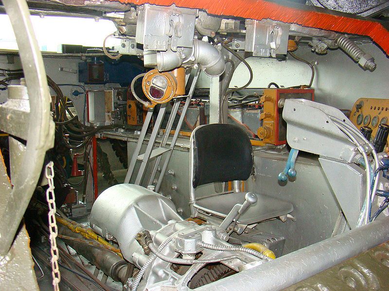
Cutaway Sherman showing transmission and driver's seat.

The U.S. Army Ordnance Department designed the Medium Tank M4 as a replacement for the Medium Tank M3. The M3 was an up-gunned development of the M2 Medium Tank of 1939, in turn derived from the M2 light tank of 1935. The M3 was developed as a stopgap measure until a new turret mounting a 75 mm gun could be devised. While it was a big improvement when tried by the British in Africa against early German tanks, the placement of a 37 mm gun turret on top gave it a very high profile, and the unusual side-sponson mounted main gun, with limited traverse, could not be aimed across the other side of the tank.
Detailed design characteristics for the M4 were submitted by the Ordnance Department on 31 August 1940, but development of a prototype was delayed while the final production designs of the M3 were finished and the M3 entered full-scale production. On 18 April 1941, the U.S. Armored Force Board chose the simplest of five designs. Known as the T6, the design was a modified M3 hull and chassis, carrying a newly designed turret mounting the M3's 75 mm gun. This became the Sherman.
The Sherman's reliability resulted from many features developed for U.S. light tanks during the 1930s, including vertical volute spring suspension, rubber-bushed tracks, and a rear-mounted radial engine with drive sprockets in front. The goals were to produce a fast, dependable medium tank able to support infantry, provide breakthrough striking capacity, and defeat any tank then in use by the Axis nations.
The T6 prototype was completed on 2 September 1941. The T6 upper hull was a single large casting. It featured a side hatch, and a single overhead hatch for the driver. In the later M4A1 production model, this large casting was maintained, although the side hatch was eliminated and a second overhead hatch was added for the bow gunner. The T6 was standardized as the M4 and production began in October.


Doctrine
Image
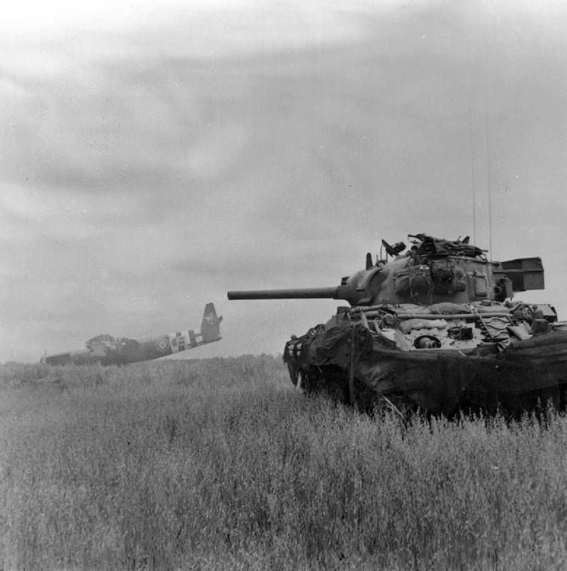
A Sherman DD tank of 13th/18th Royal Hussars in action against German troops using crashed Horsa gliders as cover near Ranville, Normandy, 10 June 1944.

As the United States approached entry in World War II, armored employment was doctrinally governed by Field Manual 100–5, Operations (published May 1941, the month following selection of the M4 tank's final design). That field manual stated:
The armored division is organized primarily to perform missions that require great mobility and firepower. It is given decisive missions. It is capable of engaging in all forms of combat, but its primary role is in offensive operations against hostile rear areas.
The M4 was, therefore, not originally intended as an infantry support tank; in fact, FM 100-5 specifically stated the opposite. It placed tanks in the "striking echelon" of the armored division, and placed the infantry in the "support echelon". The field manual covering the use of the Sherman (FM 17–33, "The Tank Battalion, Light and Medium" of September 1942) devoted one page of text and four diagrams to tank-versus-tank action, out of 142 pages. This early armored doctrine was heavily influenced by the sweeping early war successes of German blitzkrieg tactics. By the time M4s reached combat in significant numbers, battlefield demands for infantry support and tank versus tank action far outnumbered the occasional opportunities of rear-echelon exploitation.
United States doctrine held that anti-tank work was primarily to be done by towed and self-propelled anti-tank guns, both of which were referred to as 'tank destroyers'.Speed was essential in order to bring the tank destroyers from the rear to destroy incoming tanks. This doctrine was rarely followed in combat, as it was found to be impractical. Commanders were reluctant to leave tank destroyers in reserve; if they were, it was also easier for an opposing armored force to achieve a breakthrough against an American tank battalion, which would not have all of its anti-tank weapons at the front during the beginning of any attack.


U.S. production history

Image
M4A1 (76)W Sherman with cast hull

Image
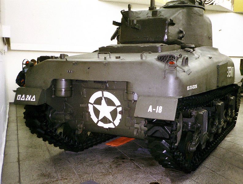
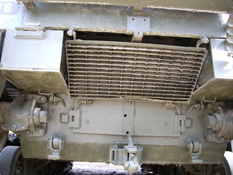
M4 and M4A1 (shown), the first Shermans, share the inverted U backplate and inherited their engine and exhaust system from the earlier M3 Medium Tank.

Image
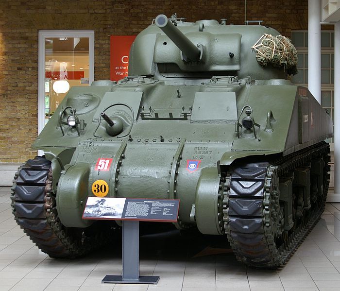
This M4A4 has extra armor plates in front of crew hatches.

The first production began with the Lima Locomotive Works on the assembly line set for tanks for British use. The first production Sherman was given over to the US Army for evaluation and it was the second tank of the British order that went to London. Named Michael probably after Michael Dewar, head of the British tank mission in the U.S., it was displayed in London and is now an exhibit at The Tank Museum, Bovington, UK.
In World War II, the U.S. Army ultimately fielded 16 armored divisions, along with 70 independent tank battalions, while the U.S. Marine Corps fielded six independent Sherman tank battalions. A third of all Army tank battalions, and all six Marine tank battalions, were deployed to the Pacific Theater of Operations (PTO). Prior to September 1942, President Franklin D. Roosevelt had announced a production program calling for 120,000 tanks for the Allied war effort, which would have created 61 armored divisions. Although the American industrial complex was not affected by enemy aerial bombing nor submarine warfare as was Japan, Germany and, to a lesser degree, Great Britain, an enormous amount of steel for tank production had been diverted to the construction of warships and other naval vessels. Steel used in naval construction amounted to the equivalent of approximately 67,000 tanks; and consequently only about 53,500 tanks were produced during 1942 and 1943.
The Army had seven main sub-designations for M4 variants during production: M4, M4A1, M4A2, M4A3, M4A4, M4A5, and M4A6. These designations did not necessarily indicate linear improvement. For example, A4 did not indicate it was better than an A3. These sub-types indicated standardized production variations, which were in fact often manufactured concurrently at different locations. The sub-types differed mainly in engines, although the M4A1 differed from the other variants by its fully cast upper hull, with a distinctive rounded appearance. The M4A4 had a longer engine system that required a longer hull and more track blocks, and thus the most distinguishing feature of the A4 was the wider longitudinal spacing between the bogies. M4A5 was an administrative placeholder designation for Canadian production. The M4A6 had a diesel engine and elongated chassis, but fewer than 100 of these were ever produced.
While most Shermans ran on gasoline, the M4A2 and M4A6 had diesel engines. The M4A2 was powered by a pair of GMC 6–71 two-stroke straight six engines, the M4A6 using a Caterpillar D-200 radial producing some 450 hp (340 kW) at 2,000 rpm, adapted from the "RD-1820" experimental diesel version of Wright Aeronautical's mass-produced Cyclone 9 aviation radial. These, plus the M4A4, which used the Chrysler A57 multibank engine, were mostly supplied to other Allied countries under Lend-Lease. "M4" can refer specifically to the initial sub-type with its Continental radial engine (R-975), or generically, to the entire family of seven Sherman sub-types, depending on context. Many details of production, shape, strength, and performance improved while in production, without a change to the tank's basic model number. These included more durable suspension units, safer "wet" (W) ammunition stowage, and stronger armor arrangements, such as the M4 Composite, which had a cast front hull section mated to a welded rear hull. British nomenclature differed from that employed by the U.S.
A 24-volt electrical system was used in the M4.


Designation Main Armament Hull Engine
M4 75 mm welded gasoline Continental R975 radial
M4(105) 105 mm howitzer welded gasoline Continental R975 radial
M4 Composite 75 mm cast front, welded sides gasoline Continental R975 radial
M4A1 75 mm cast gasoline Continental R975 radial
M4A1(76)W 76 mm cast gasoline Continental R975 radial
M4A2 75 mm welded GM 6046 diesel (conjoined 6-71s)
M4A3W 75 mm welded gasoline Ford GAA V8
M4A3E2 "Jumbo" 75 mm (some 76 mm) welded gasoline Ford GAA V8
M4A3E8(76)W "Easy Eight" 76 mm welded gasoline Ford GAA V8
M4A4 75 mm welded; lengthened gasoline Chrysler A57 multibank
M4A6 75 mm cast front, welded sides; lengthened diesel Caterpillar D200A radial
M4 Sherman: comparison of key production features of selected models

Image
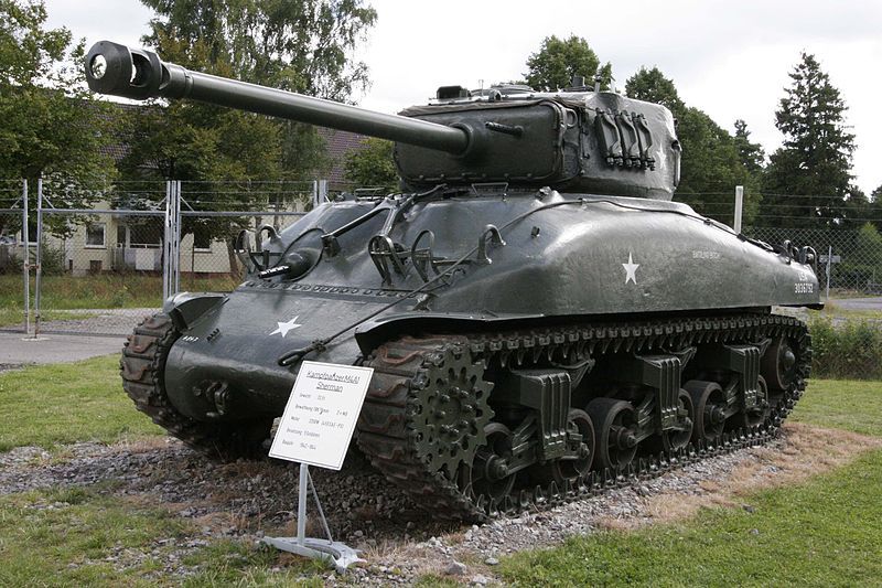
A 76 mm M1 gun-equipped Easy Eight Sherman

Early Shermans mounted a 75mm medium-velocity general-purpose gun. Although Ordnance began work on the Medium Tank T20 as a Sherman replacement, ultimately the Army decided to minimize production disruption by incorporating elements of other tank designs into the Sherman. Later M4A1, M4A2, and M4A3 models received the larger T23 turret with a high-velocity 76 mm M1 gun, which reduced the number of high-explosive and smoke rounds carried and increased the number of anti-tank rounds. Later, the M4 and M4A3 were factory-produced with a 105 mm howitzer and a distinctive mantlet, which surrounded the main gun, on the turret. The first standard-production 76 mm gun Sherman was an M4A1, accepted in January 1944, which first saw combat in July 1944 during Operation Cobra. The first standard-production 105 mm howitzer Sherman was an M4 accepted in February 1944.
In June–July 1944, the Army accepted a limited run of 254 M4A3E2 Jumbo Shermans, which had very thick hull armor and the 75 mm gun in a new, heavier T23-style turret, in order to assault fortifications. The M4A3 was the first to be factory-produced with the option of the horizontal volute spring suspension (HVSS) system, with wider tracks to distribute weight, and the smooth ride of the HVSS. Its experimental E8 designation led to the nickname "Easy Eight" for Shermans so equipped. Both the Americans and the British developed a wide array of special attachments for the Sherman, although few saw combat, remaining experimental. Those that saw action included the bulldozer blade for the Sherman dozer tanks, Duplex Drive for amphibious Sherman tanks, R3 flamethrower for Zippo flame tanks, and the T34 60-tube Calliope 4.5" rocket launcher mountable atop the Sherman's turret. The British variants (DDs and mine flails) formed part of the group of specialized vehicles collectively known as "Hobart's Funnies" (after Percy Hobart, commander of the 79th Armoured Division).
The M4 Sherman's basic chassis was used for all the sundry roles of a modern mechanized force: roughly 50,000 Sherman tanks, plus thousands more derivative vehicles under different model numbers. These included the M10 Wolverine and M36 tank destroyers; M7B1, M12, M40, and M43 self-propelled artillery; the M32 and M74 "tow truck"-style recovery tanks with winches, booms, and an 81 mm mortar for smoke screens; and the M34 (from M32B1) and M35 (from M10A1) artillery prime movers.


Image
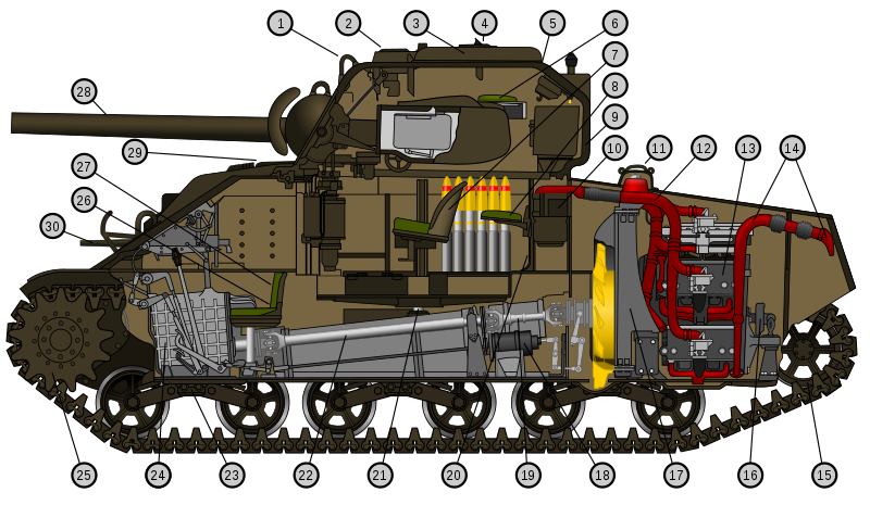
M4A4 Cutaway: 1 - Lifting ring, 2 - Ventilator, 3 - Turret hatch, 4 – Periscope, 5 – Turret hatch race, 6 – Turret seat, 7 – Gunner's seat, 8 – Turret seat, 9 – Turret, 10 – Air cleaner, 11 – Radiator filler cover, 12 – Air cleaner manifold, 13 – Power unit, 14 – Exhaust pipe, 15 – Track idler, 16 – Single water pump, 17 – Radiator, 18 – Generator, 19 – Rear propeller shaft, 20 – Turret basket, 21 – Slip ring, 22 – Front propeller shaft, 23 – Suspension bogie, 24 – Transmission, 25 – Main drive sprocket, 26 – Driver's seat, 27 – Machine gunner's seat, 28 – 75 mm gun, 29 – Drivers hatch, 30 – M1919A4 machine gun.

That's that bit out of the way appologies if it was too long

Part 1 of the build will be up soon
User avatar
gaz45
Chief Warrant Officer 3
Posts: 1971
Joined: Mon Jan 06, 2014 3:35 pm
Location: Nottingham uk
Great Britain

Re: Dragon 1:35 Sherman k.III

Post by gaz45 »

Right here we go part 1

Before i start just a little information to anyone doing this kit you will find that on some sprues there are different parts with the same number so make sure your cutting off the right one

To start with there are 2 choices of wheel open or filled in centres and from the pictures i have seen they are filled so that is what i will go with,
Also the instruction are not clear wether or not the wheels and suspension is movable but with a little time and careful glueing i have managed to have them workable

Image

Image

So with 1 complete here are the other 5

Image

and the sprockets again there are 2 choices

Image

Image

The back plate with the exhausts here i was going to drill out the exhaust more but has they are small i did't want to drill straight through

Image

Image

Next the lower hull the suspension fittings on along with the suspension and the wheels along with the back plate and the tension wheels which i have left free untill the tracks go on

Image

Image

Image

Image

Image

Image

Image

Finally for today the front plate, now on here the 2 plates where the tow hooks attach there are 2 lugs on each but no locating holes on the plate so in stead of drilling holes i sanded off the lugs

Image

Image

Image

Image

Image

That is all for now thanks for taking a look
privatepete
First Lieutenant
First Lieutenant
Posts: 3871
Joined: Thu Dec 11, 2014 1:13 pm

Re: Dragon 1:35 Sherman k.III

Post by privatepete »

Hi Gas,great start, you can't go wrong with a Sherman, good luck with the rest of the build.
User avatar
gaz45
Chief Warrant Officer 3
Posts: 1971
Joined: Mon Jan 06, 2014 3:35 pm
Location: Nottingham uk
Great Britain

Re: Dragon 1:35 Sherman k.III

Post by gaz45 »

Thanks mate
User avatar
Stokesy44
Major General
Major General
Posts: 8227
Joined: Thu Jun 18, 2015 10:13 am
Location: The Midlands, UK
Great Britain

Re: Dragon 1:35 Sherman k.III

Post by Stokesy44 »

Looking good there mate.

What sort of winter setting will you be going for? Not much snow in the desert (unless you're Bravo Two Zero!)
Its been tried and tested, it works! So don't blame the system if you're no good. :doh:
User avatar
gaz45
Chief Warrant Officer 3
Posts: 1971
Joined: Mon Jan 06, 2014 3:35 pm
Location: Nottingham uk
Great Britain

Re: Dragon 1:35 Sherman k.III

Post by gaz45 »

Not sure as yet never done a winter cam before
User avatar
gaz45
Chief Warrant Officer 3
Posts: 1971
Joined: Mon Jan 06, 2014 3:35 pm
Location: Nottingham uk
Great Britain

Re: Dragon 1:35 Sherman Mk.III

Post by gaz45 »

Part 2
Before carrying on i have to paint a couple of periscopes flat black for this i used Ultimate black primer

Image

The driver and gunners hatches can be posed open or closed i'm going with closed as it's winter

Image

Image

The next part of the build includes some PE the lights and the machine gun
the lights are clear parts so i will be adding them at the end
Bending the PE with my PE bender

Image

Image

The first one is just a 90 degree bend

Image

Image

The next 2 piece of PE are for the light guards these are going to be a bit tricky to bend as i don'i have the rolling tools for this If it looks pants i'll have to use the kit plastic ones.
First one not too bad

Image

For shaping these i used the handle of a round file and rolled it over the PE on my cutting matt
I know they are not perfect but for my first attempt i think they will do the job

Image

Image

Right time to attach these with the other parts for the front

Image

Image

Image

Now to the rear of the hull which includes some more PE which will be shaped as i did with the front ones, some hatch covers and the cover for the engine

Image

on the engine plate i needed to remove a stub which i did with my cutters and sanded it smooth with a Ultimate sander

Image

Image

Image

Image

To finish with today i'll add the engine covers which would look good in PE but the kit ones look nice and detailed and with an 0.8mm bit in my pin vice i drilled out the holes for the tools

Image

Image

That's all for now thanks for taking a look and for all your comments
privatepete
First Lieutenant
First Lieutenant
Posts: 3871
Joined: Thu Dec 11, 2014 1:13 pm

Re: Dragon 1:35 Sherman k.III

Post by privatepete »

Hi gaz I don't want to be a bearer of bad news but have you put the rear tow hitch the wrong way up , I think the locking handle should be at the top/towards the exhaust ,sorry
User avatar
gaz45
Chief Warrant Officer 3
Posts: 1971
Joined: Mon Jan 06, 2014 3:35 pm
Location: Nottingham uk
Great Britain

Re: Dragon 1:35 Sherman k.III

Post by gaz45 »

Sorry Pete could you explan i'm not an armor builder and not sure what you mean
User avatar
gaz45
Chief Warrant Officer 3
Posts: 1971
Joined: Mon Jan 06, 2014 3:35 pm
Location: Nottingham uk
Great Britain

Re: Dragon 1:35 Sherman k.III

Post by gaz45 »

Scrap the last comment now i see what you mean i'll have a closer look thanks for pointing that out.
I've looked and it's the way it is shown in the instructions
privatepete
First Lieutenant
First Lieutenant
Posts: 3871
Joined: Thu Dec 11, 2014 1:13 pm

Re: Dragon 1:35 Sherman k.III

Post by privatepete »

I'm not saying you or the instructions are wrong.

Image

Image

Image

Thought I would just sheare these's pic
User avatar
gaz45
Chief Warrant Officer 3
Posts: 1971
Joined: Mon Jan 06, 2014 3:35 pm
Location: Nottingham uk
Great Britain

Re: Dragon 1:35 Sherman k.III

Post by gaz45 »

Thanks mate I have turned it around I have also seen some that were to the side
Bissyboat
Sergeant Major of the Army
Posts: 1254
Joined: Sun Jan 05, 2014 9:49 pm
Location: Norway

Re: Dragon 1:35 Sherman k.III

Post by Bissyboat »

Nice job on the dinky details. :thumb2:
Where`s my dinghy?
User avatar
gaz45
Chief Warrant Officer 3
Posts: 1971
Joined: Mon Jan 06, 2014 3:35 pm
Location: Nottingham uk
Great Britain

Re: Dragon 1:35 Sherman k.III

Post by gaz45 »

Cheers mate
User avatar
gaz45
Chief Warrant Officer 3
Posts: 1971
Joined: Mon Jan 06, 2014 3:35 pm
Location: Nottingham uk
Great Britain

Re: Dragon 1:35 Sherman k.III

Post by gaz45 »

Here we are with Part 3

On the back plate of the upper hull there is an option to drill out some holes or use PE bolt heads
I'm going with the bolt heads first if this fails i'll drill out the holes instead.
So the PE done this was tricky with it being so small and i need to practice with the CA glue and small parts and a couple more tools added

Image

Image

Next a couple more periscopes need to be painted flat black before assembly

Image

Now for the cappola this next part was a little tricky to work out from the instructions. Some very tiny parts that are hard to sand let alone glue in place.
These hatches con also be open/closed and even though i'm having them closed i am still going to add the interior parts it's all practice

Image

Image

Next up the turret here the one piece barrel makes things easier, the instructions don't day to glue or not to glue the mechanism I have not glued this so as to keep it workable

Image

Image

Image

With these parts dry it was time to build up the turret

Image

Image

When it came to bending the PE which i assumed needed to be bent in half it snapped so i had to CA glue it back together

Image

Image

Image

Image

Image

Image

Image

The storage box on the back of the turret can be open/closed on or off f you decide not to put this on there is a choice of 3 PE emblems that go on the back of the turret with this in mind i'm going to add the box ans show it closed

Image

Image

Image

Image

Image

The last part for today is the tow cable.
There is a nice fit between the metal cable and the cable ends

Image

Image

Image

and the PE clasps they were very tricky to bend

Image

Image

Image

Now the cable at the front is shown attached to one off the towing eyes this was a problem has the cable end would not fit over the ends of the eye so i'll have to have this a little shorter and clamped to the lower hull as the other option shows

Image

So with the upper hull glued in place the tow cable was finished

Image

That is it for this part there is a lot more of the PE n the next part so i'll save that for another day.

Thanks for taking the time to look and comment
User avatar
DC87
Chief Warrant Officer 2
Posts: 1799
Joined: Wed Jun 05, 2013 7:16 pm
Location: Exeter, Devon, UK
England

Re: Dragon 1:35 Sherman k.III

Post by DC87 »

Mighty fine build up work so far.
Dan C

Filling the workbench with:
Sopwith Snipe late post war
WW1 RFC SE5a

WW1-1/32 Snipe
Workbench gets full with models being built - Buys another workbench!

Image
User avatar
gaz45
Chief Warrant Officer 3
Posts: 1971
Joined: Mon Jan 06, 2014 3:35 pm
Location: Nottingham uk
Great Britain

Re: Dragon 1:35 Sherman k.III

Post by gaz45 »

thanks mate
User avatar
gaz45
Chief Warrant Officer 3
Posts: 1971
Joined: Mon Jan 06, 2014 3:35 pm
Location: Nottingham uk
Great Britain

Re: Dragon 1:35 Sherman k.III

Post by gaz45 »

So here we are Part 4 the final part bof the build which apart from the tracks is PE I don't think i've had so much PE on any one model so this will be a test in how my skills are progressing,I do need to take more care with the CA glue with these parts I guess it's a skill that developes over time the more you do.

That is one part attached the same needs to be done on the other side then on to the next part. The other side turned out better than the first side , I guess thats how it goes lol.

Image

Image

This next part calls for some smaller lengths of PE to be bent into rectangles then glued onto the longer lengths i'm hoping to o this on the PE bender.
The bending was quite easy i just needed to complete the last bends with some tweezers i'll glue the ends when they are all finished.

Image

Image

Image

Image

Image

Image

Image

Image

The front mud flaps i guess they are called there are bends and a curve i'm not sure of the best way of doing this but here goes.
The first side of this didn't go well with the PE snapping which i didn't take pics of so i'll try again on the other one

Image

After a quick dry fit using white tac

Image

Image

Image

Image

Image

Image

This is how it came out

Image

Image

This is the last part of PE and for the build the stowage box for the front

Image

Image

Image

Image

Image

So that is the build complete
Thank you for taking the time to look and to cooment it is much appreciated.
User avatar
spock1701
Master Sergeant
Master Sergeant
Posts: 449
Joined: Wed Apr 29, 2015 1:58 pm
Location: Upstate New York
United States of America

Re: Dragon 1:35 Sherman k.III

Post by spock1701 »

Nice work on the PE there, mate. Looks superb :thumb1:
There is always time for modeling.
Bissyboat
Sergeant Major of the Army
Posts: 1254
Joined: Sun Jan 05, 2014 9:49 pm
Location: Norway

Re: Dragon 1:35 Sherman k.III

Post by Bissyboat »

Careful precision work going into every little detail. :th:
Where`s my dinghy?
User avatar
gaz45
Chief Warrant Officer 3
Posts: 1971
Joined: Mon Jan 06, 2014 3:35 pm
Location: Nottingham uk
Great Britain

Re: Dragon 1:35 Sherman k.III

Post by gaz45 »

thanks guys
User avatar
Tomcat64
Brigadier General
Brigadier General
Posts: 7034
Joined: Thu Sep 22, 2016 3:24 pm
Location: Swindon, UK
England

Re: Dragon 1:35 Sherman k.III

Post by Tomcat64 »

Nice, detailed step by step build Gaz, and great work on all that PE - not something I've had to face yet!
Cheers, Neil

On the Bench:
Tamiya 1/35 PzKpfwIB
Tamiya 1/35 Willys Jeep
Revell 1/72 Millennium Falcon
User avatar
Kevthemodeller
Lieutenant Colonel
Lieutenant Colonel
Posts: 5596
Joined: Sat Mar 26, 2016 8:31 am
Location: Newton Abbot UK
England

Re: Dragon 1:35 Sherman k.III

Post by Kevthemodeller »

Lovely work going on here :th:
Kev

On the bench:
Border Model FOCKE-WULF W190A-8 R2 - 8
privatepete
First Lieutenant
First Lieutenant
Posts: 3871
Joined: Thu Dec 11, 2014 1:13 pm

Re: Dragon 1:35 Sherman k.III

Post by privatepete »

Hi really looks great, like all the extra PE work, keep it up :th:
User avatar
pourquoi61
Sergeant Major of the Army
Posts: 1289
Joined: Tue Feb 16, 2016 12:57 pm
Location: Ilkeston, Derbyshire
Great Britain

Re: Dragon 1:35 Sherman k.III

Post by pourquoi61 »

Fantastic so far, only the brits would put a shopping trolley on the front of a tank. :scratch:: :scratch::
Image
User avatar
gaz45
Chief Warrant Officer 3
Posts: 1971
Joined: Mon Jan 06, 2014 3:35 pm
Location: Nottingham uk
Great Britain

Re: Dragon 1:35 Sherman k.III

Post by gaz45 »

Thanks for all your comments
User avatar
gaz45
Chief Warrant Officer 3
Posts: 1971
Joined: Mon Jan 06, 2014 3:35 pm
Location: Nottingham uk
Great Britain

Re: Dragon 1:35 Sherman k.III

Post by gaz45 »

Part 5

I planned to do my first dio for this aswell
This is what i plan to do with the fence made from matchsticks
I will appoligise now if any of this looks out of scale but this is my first attempt at a dio

Image

I thought i'd start with the fence so i kew what room i had to work with at first i used CA glue but for some reason it didn't stick the matchsticks too well so in the end i used PVA

Image

Image

Image

Image

Image

Image

I have used DAS on the base i have never used this stuff before so i wasn't sure how to use it.
I put a thin layer of PVA down first before adding the clay as i thought that this would stick the clay to the base which in hind sight maybe was not a good idea as the glue dried quicker than the clay causing it to crack.
I will be putting another layer on but this time no glue

Image

Image

Image

Image

Image

Image

With that first part out of the way i primed the tank and the tracks in Ultimate black primer

Image

Image

Image

While the primer was drying i started another layer of clay on the base

Image

And to finish off with I base coated the tank using Mr hobby H-27 Tan which turned out ok although a bit on the shiny side

Image

Image

Image

Image

Image

Image

Image

Image

Image

Image

Image

That's all for this part thanks for taking the time to look and comment
Bissyboat
Sergeant Major of the Army
Posts: 1254
Joined: Sun Jan 05, 2014 9:49 pm
Location: Norway

Re: Dragon 1:35 Sherman k.III

Post by Bissyboat »

A lot of good work here. :th:
Where`s my dinghy?
User avatar
gaz45
Chief Warrant Officer 3
Posts: 1971
Joined: Mon Jan 06, 2014 3:35 pm
Location: Nottingham uk
Great Britain

Re: Dragon 1:35 Sherman k.III

Post by gaz45 »

Thanks mate
privatepete
First Lieutenant
First Lieutenant
Posts: 3871
Joined: Thu Dec 11, 2014 1:13 pm

Re: Dragon 1:35 Sherman k.III

Post by privatepete »

Hi Gaz looks good in that Tan colour, be great to see it finish,keep up nice work :th:
User avatar
gaz45
Chief Warrant Officer 3
Posts: 1971
Joined: Mon Jan 06, 2014 3:35 pm
Location: Nottingham uk
Great Britain

Re: Dragon 1:35 Sherman k.III

Post by gaz45 »

Thanks guys
User avatar
gaz45
Chief Warrant Officer 3
Posts: 1971
Joined: Mon Jan 06, 2014 3:35 pm
Location: Nottingham uk
Great Britain

Re: Dragon 1:35 Sherman k.III

Post by gaz45 »

Part 6

Right the second layer of clay was put down and when that was all dry i masked the edges of the frame ready for painting.
First it was primed with Ultimate black primer.
For the base coat i used Model air RLM 81 olive drab with a few drops of the Ultimate primer to darken it down a little. When that was dry i sprayed over a light coat of the olive drab.
After that i sprayed on some Model air RLM 82 camo green to give this a green shade i'm not sure the pics show this well but it will have a dusting of snow on it at the end.

Image

Image

Image

Image

Now on to the fence which keeps falling apart i'll have to rebuild this on the base

Image

So while i was waiting for the glue to dry on the fence i painted on the camo color on the tank using Mr hobby H-32 Field gray (1) this was done freehand so it looks a little messy but as with the base it will have some snow on it

Image

Image

Image

Image

Image

Image

Image

With the fence in place and all dry i decided to color this with some oils i used some thinned Abteilung 502 engine grease funny enought that's the closest i have for a wood effect

Image

Image

As the oil will take some time to dry i did the detail painting on the tank

The exhaust was in Mr hobby H-76 burnt iron
The wooden tool handles in Revell 37 reddish brown
The metal parts such as the machine guns, spade, axe and the track tools i used Model air steel
The tow cable was also painted with the burnt iron
Then the tires with Mr hobby H-12 flat black

Image

Image

Image

Image

Image

Image

That's all for now
Thanks for taking a look and for all your comments
Bissyboat
Sergeant Major of the Army
Posts: 1254
Joined: Sun Jan 05, 2014 9:49 pm
Location: Norway

Re: Dragon 1:35 Sherman k.III

Post by Bissyboat »

Things are shaping up nicely on your Sherman build. :th:
Where`s my dinghy?
User avatar
gaz45
Chief Warrant Officer 3
Posts: 1971
Joined: Mon Jan 06, 2014 3:35 pm
Location: Nottingham uk
Great Britain

Re: Dragon 1:35 Sherman k.III

Post by gaz45 »

Cheers mate
User avatar
gaz45
Chief Warrant Officer 3
Posts: 1971
Joined: Mon Jan 06, 2014 3:35 pm
Location: Nottingham uk
Great Britain

Re: Dragon 1:35 Sherman k.III

Post by gaz45 »

Final part
Unfortunatly i have lost the photos to the next step putting on the snow effect
This again is a first for me for this i used Deluxe materials scenic snow.
So what i did was to brush on the glue where i wanted the snow to be such as the horizontal parts of the fence, the tree and the base and sprinkled on the snow you can do this several times letting each layer dry before adding more till you get the effect that you want.

Image

Image

Image

Image

Image

The same process was used on the tank

Image

Image

Image

Then when that was all dry i placed the tank on the base then added some more of the snow to the whole thing to marry the two together.

This was the inspiration of the dio

Image

So here it is all finished

Image

Image

Image

Image

Image

Image

So there we are i will post the final photos later
Thanks for looking and for all your comments.
Bissyboat
Sergeant Major of the Army
Posts: 1254
Joined: Sun Jan 05, 2014 9:49 pm
Location: Norway

Re: Dragon 1:35 Sherman k.III

Post by Bissyboat »

Nice progress on the dio. :th:
Where`s my dinghy?
User avatar
DarrenCo
Corporal
Corporal
Posts: 84
Joined: Mon Apr 10, 2017 2:03 pm
Great Britain

Re: Dragon 1:35 Sherman k.III

Post by DarrenCo »

Looking good! another put on my to do list
User avatar
gaz45
Chief Warrant Officer 3
Posts: 1971
Joined: Mon Jan 06, 2014 3:35 pm
Location: Nottingham uk
Great Britain

Re: Dragon 1:35 Sherman k.III

Post by gaz45 »

Thanks guys
Post Reply

Return to “Build Threads”